CW at 55W Continuous
Testing homebrew units built from scratch.
I have now, at long last, finally gotten around to homebrewing a balun and unun. Both are ratio 9:1, intended for use with non-resonant wire antennas while operating portable on all HF bands.
|
|
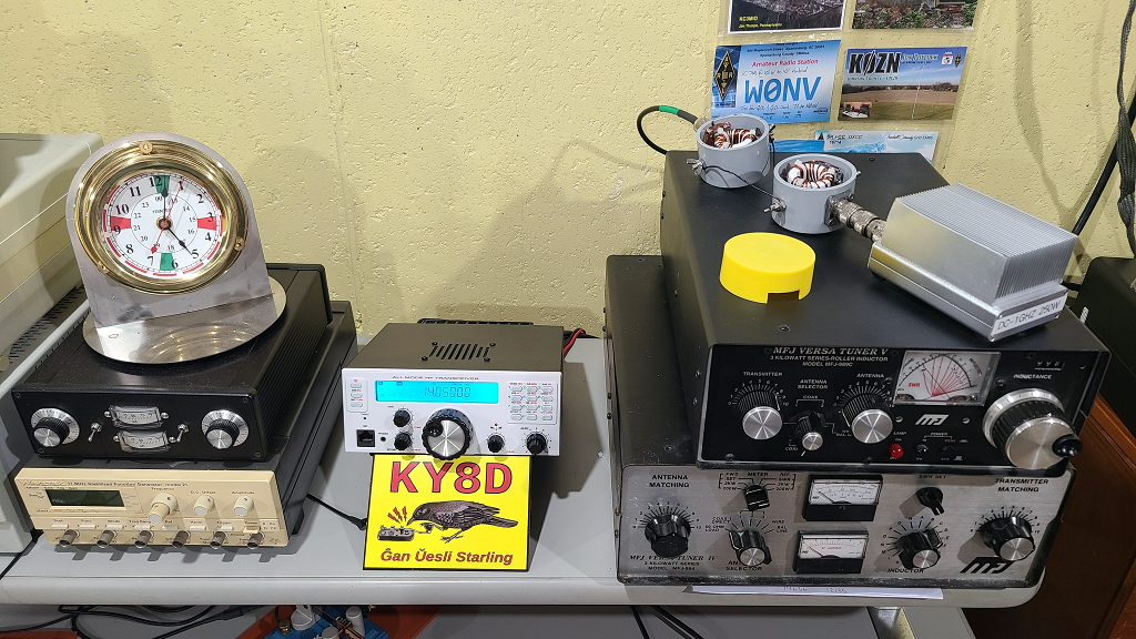
Above you see both units being tested together atop the black antenna tuner at right. Both being 9:1 ratio, I just hooked them back-to-back as throughput to a plain jane, 50 Ohms, dummy load. Test consisted of 20wpm CW at 55W (full output of the Mission RGO One) for 30 minutes. At which point the dummy load itself got quite warm, but not the cores.
My, ahem, temperature probe, was an index finger touching each core at end of test (after securing RF power, of course).
While not a test of absolute max power for the transformers themselves, still a solid guarantee they’ll hold up during a proper CW ragchew while operating portable, which is all they’ll ever see.
Before committing to a test at full power, first I ran some tests at no power, as below. In the top instance, at 29-30 MHz, which gave the worst case at 1.5:1 SWR.
|
|
Prior even to then, firstly I checked against my possibly having connected the windings wrong. All was well. The resistor is 470 Ohms, carbon composition. Shown is 1.2:1 SWR obtained at 9.5-10.5 MHz.
|
|
One of the goals was compact size. This secondary to supporting full rag chews (even marathons) while portable at 55W on battery power.
These are Fair-Rite 5943002701 (Amidon FT140-43 equivalent). Each unit consists of two cores, the first for each being a 1:1 current balun as common-mode choke, the second transforming Z at 50:450 Ohms. The windings are from a spool of 16AWG enameled magnet wire that I’ve hoarded for decades.
Prior to winding, I wrapped each core with a double layer of 1/2 inch Teflon tape, mostly as protection for the magnet wire. At the time, I worried (needlessly, as proven above) whether it might too much impede heat dissipation.
The balun and unun are both trifilar wound, eight turns for each (as counted through the center). Both are alike save for how the interconnections are made.
|
|
The common-mode-chokes are alike for each, bifilar wound, thirteen turns (through the center).
|
|
The housings are 2-inch PVC conduit caps, closed off by cap plugs, size 2 5/8. Those being round, the procedure was thus:
|
|
The antenna-wire terminals are #12-32 x 3/4, 316 stainless, button head screws. Force-forming tight, weatherproof threads proved difficult. Three turns with a tap gave me enough of a head start on that.
|
|
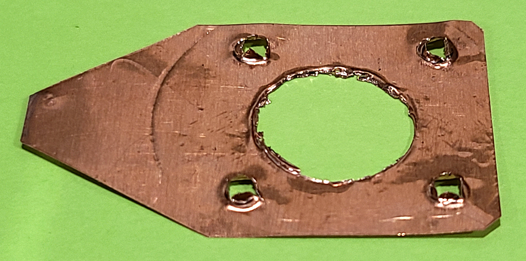
On the inside, grounding is by point-contact with four stainless lock nuts against copper foil (got, as I recall, from a hobby art store.). The central hole I cut out by tracing a pointed awl around the inside of a clamped-down washer. The screw holes I punched through with the same awl. The screw holes being ragged helps to make contact with the threads of the screw when mashed down by the nuts.
As the terminals had to be mounted first, leads from the windings required soldering ex-post-facto. As a heat sink, first I spun two extra nuts plus also a wing nut onto the screw threads. The screw head then drew heat away from the o-ring while I mated leads and terminal with 63/37 solder using a 60W iron.
|
|
The button head screws and terinals, being flat, required a means to interface the curved inside. For this I employed small Viton orings which I happened to have on hand.
Content presented below is an SVG document which I authored in Inkscape. The 3D models I generated in Rhino 7. If and when I build other types for myself, then will I document those the same way.
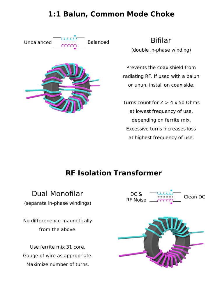
First we have the 9:1 units. You could wind them monofilar, as shown at top. Arguments go both ways for which is best. Multi-filar makes for simpler construction, but at the cost of there existing high differences of RF potential between adjacent turns. Thus is capacitive charge much increased. An increased risk of arcing therefor. With monofilar, that less of a worry, turn to turn, but very much increased between the first and last turns. Best to insure a wide gap between the ends with monofilar, accomplished by winding on less than the full circumference.

Now for the 1:1 common-mode choke. That plus also a close relation, as you will see.
In a separate poject, I have twice employed the alternative winding scheme below. Construction was identical save for each balun having but a single toroid: Fair-Rite 5952020801, having an AL of 283, 4 turns each side. (Purpose was to connect a remote auto-tuner at near ground level via window line to a random doublet at 12m elevation.)
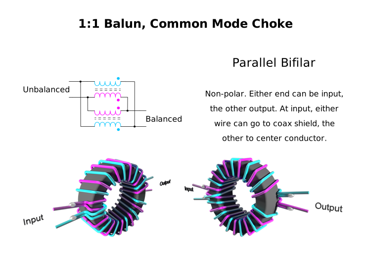
Here is a Link to another how-to for this same concept.
So was I for a long time. Allow me to clarify as it was explained to me.
Dismiss from your mind all considerations of clockwise versus counter-clockwise. When it comes to a toroid, those directions have no application at all.
Employ just only the magnetic Right Hand Rule. Consider the just only the input wires. Do they enter into the center of the toroid both from the same side, or not? If they do, then flux is in phase for Common Mode. Which is to say the flux from both wires add together.
If instead the input wires enter the center from opposite sides, then their flux is out of phase. The two fluxes subtract from each other. They cancel out.
Just like a spring, flux resists further input of energy and wants to release any energy it has stored. Thus in-phase flux opposes the very current which created it. This makes for a barrior proportional in strength to the source current. And subtractive, canceled-out flux represents the absence of said barrior.
And so, in relation to Common Mode, employ the right hand rule to either both wires at the input, or instead to both wires at the output. And in relation to the wanted RF Signal, employ the right hand rule to either wire at the input, then to the other wire at the output.
The 1:1 balun (common-mode choke) goes between coax and the 9:1, regardless of type. When the 9:1 is a balun, then it goes without saying that antenna wires will be two, both equal length (or maybe a loop). Polarity is a non-issue with this particular type of balun, it being perfectly symmetrical.
When the 9:1 is an unun, however, then polarity matters greatly. The unun’s counterpoise side must connect through to the coax shield, the unun’s 50Z side to coax center. A counterpoise wire is also required, but need not be of equal length. You can’t do without, because of the common-mode choke. Without the CMC in place, then yes you could … but doing so would expose your rig to common-mode RF. Which, at 55W, would not be treating it kindly.
Links to websites on the same topic.
Latin for “Let the moocher beware”. I composed this for me, and employed it with glee. I share it here with you for free, but offered without even so much as the smell of a dead warranty (or wheriot, as the case may be). Whatsoever disasters of cosmic proportion as may result from the use of this information, any and all culpability rests wholly and solely with the user.
My contact email and postal address are on QRZ.com for call sign KY8D