FRI-Match with Reversing Switch
Homebrewing a FRI-Match Antenna Tuner.
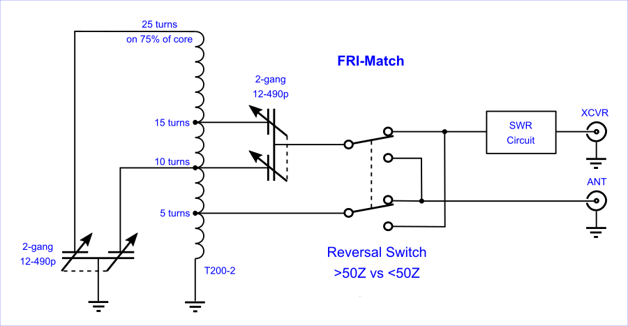
First proposed by PA0FRI, these units, while small and compact, tolerate 100W power easily. Although affording less range than a T-Match, they exhibit higher efficiency.
An FRI-Match is easily built from just only a hand-wound toroid plus a matched pair of cheap and ubiquitous, narrow-gap air capacitors. Having only two knobs, tuning is uncomplicated (if, at times, just a bit touchy).
An FRI-Match differs from its elder cousin the Z-Match by coupling capacitively instead of via a link coil. Mirror images of the same circuit step Z either up or down. Whereas some builders simply swap XCVR for ANT at the coax connectors, I installed a reversing switch so that I might build in an SWR meter.
|
|
My own unit as built and described here initially proved disappointing, but only at first. I had intended that it might tune an untested math-cut 30m dipole during a trip to South Africa. With said antenna strung (as dictated by unforseen necessity) instead as a horizontal V, the FRI-Match did not serve well. The rig in question was a QRP-Labs QCX+ and matching 50W amp without benefit of built-in automatic ATU.
More recently I tried out the FRI-Match again. This time on a low-slung, non-resonant doublet of 11.29m length per leg fed via a 9:1 balun. That was supposed to have been a combination sufficient to afford all bands to a XCVR equiped with built-in automatic ATU. It proved not the case. Not even close. But after inserting the FRI-Match in-between, then I could easily tune the wire for 12m through 40m inclusive.
At a guess, the variable capacitors may be a little suspect. This for their range of 12-490pF (versus a classic FRI-Match built with caps ranging 5-470pF). I’ll update this page with more precise info as soon as I have it.
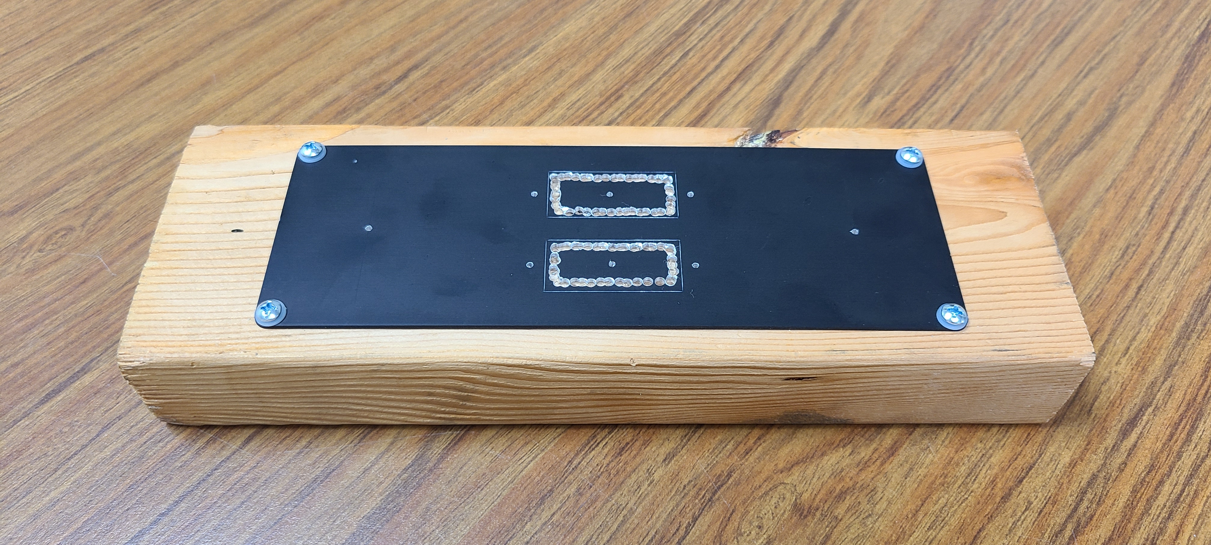
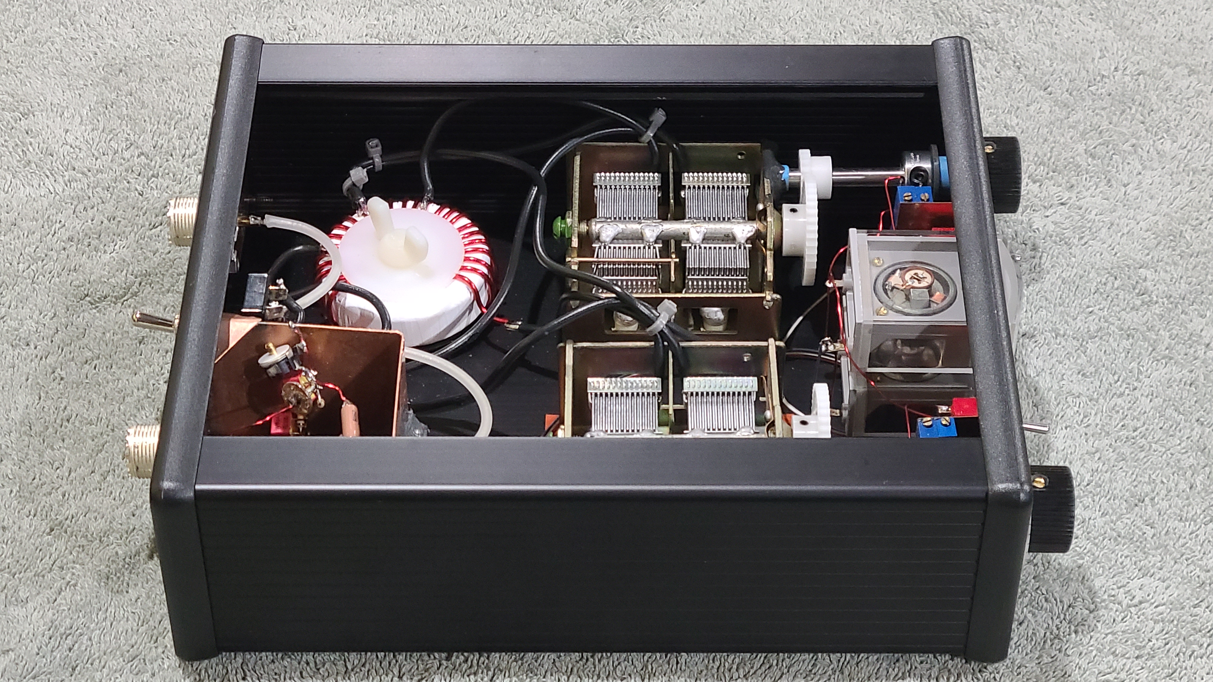
The case is by Hammond, model 1455U2201BK. For the front plate, lacking a rectangular punch, I drilled out, then filed smooth holes to fit the Russian 100uA meter movements.
|
|
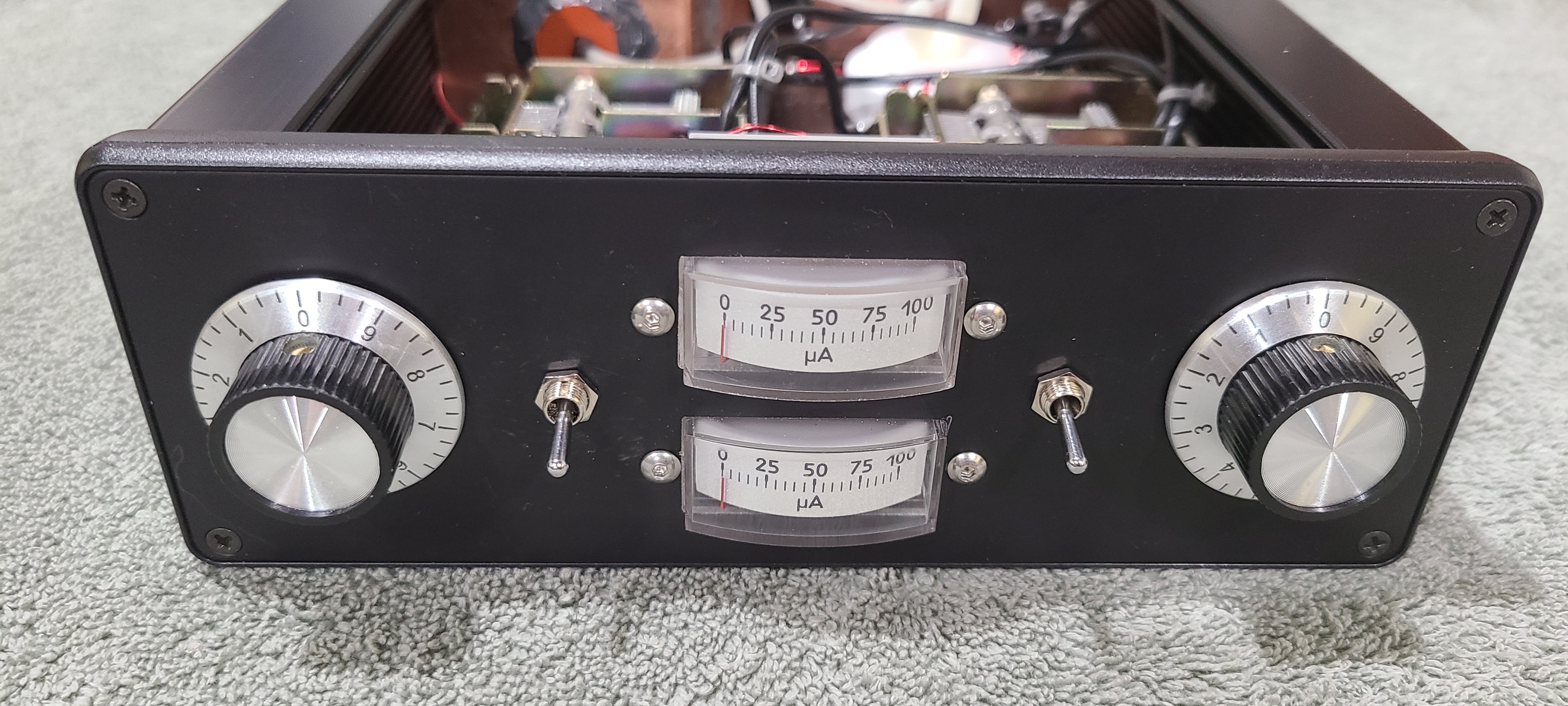
The finished face came out rather nice.
|
|
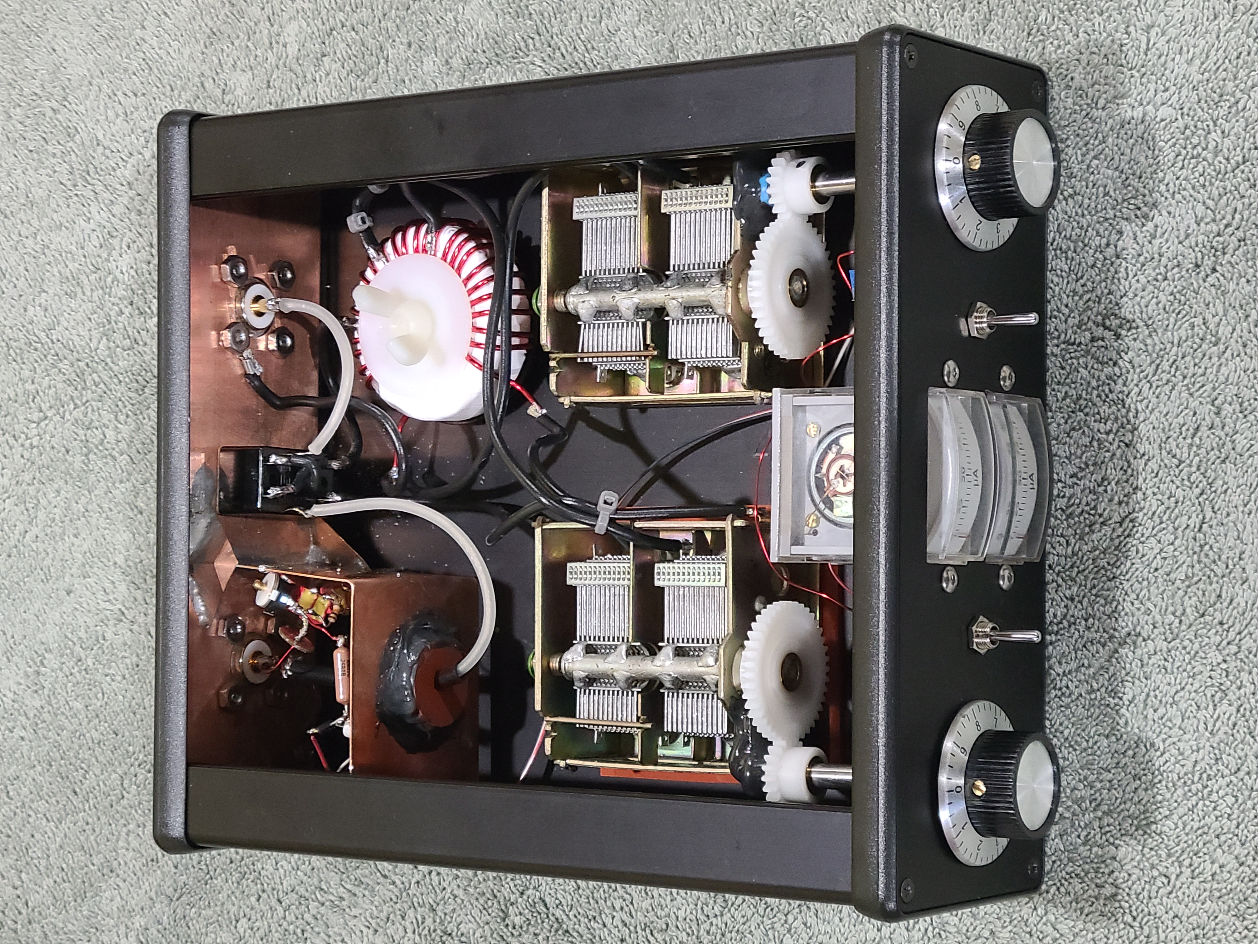
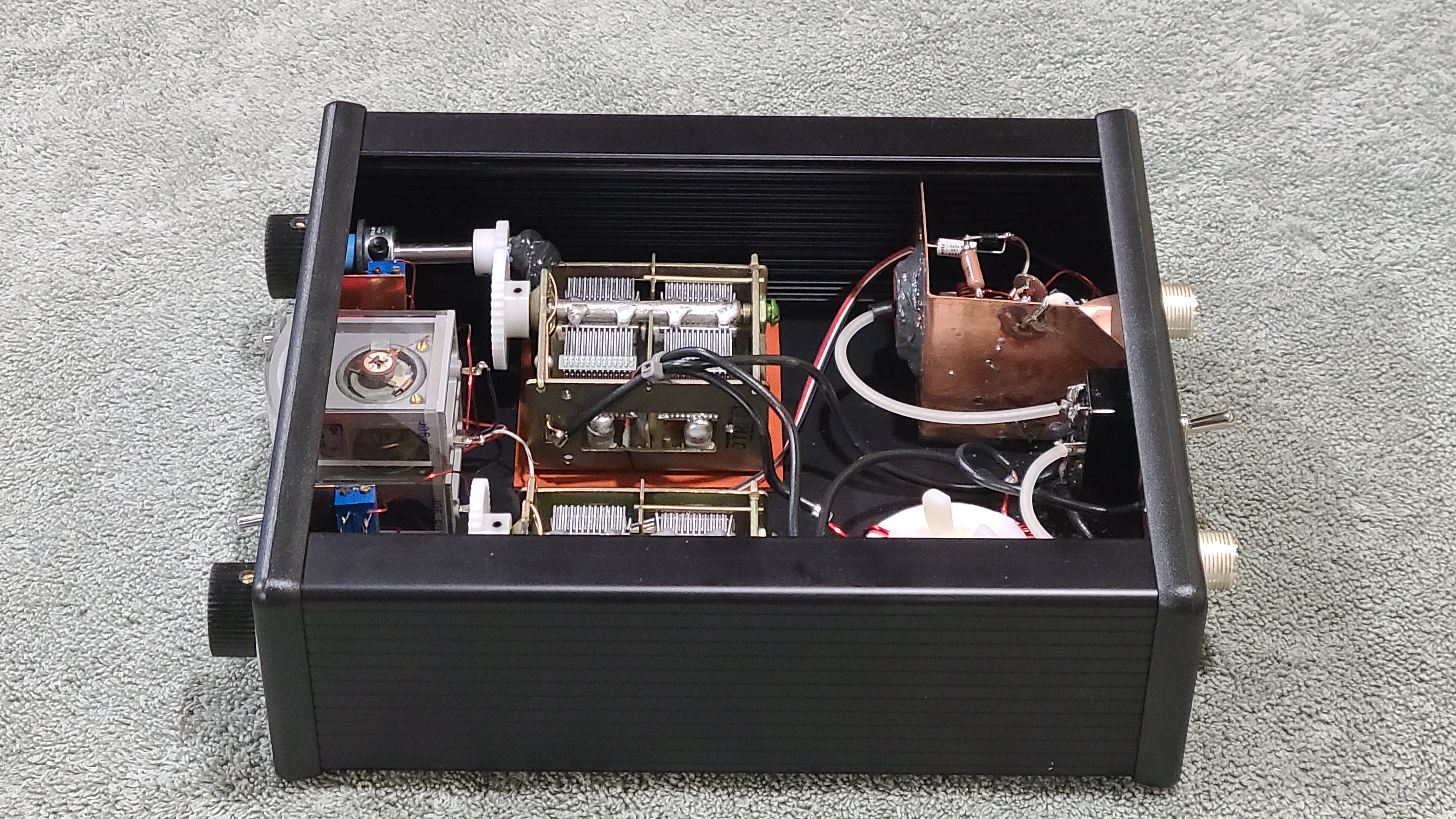
Intended for portable use, I packed the components in nice and snug.
|
|
|
|
|
|
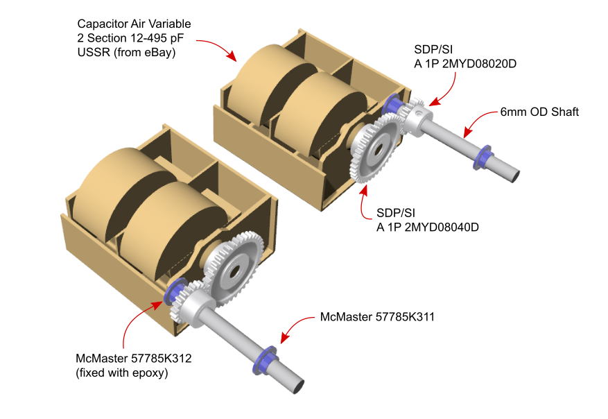
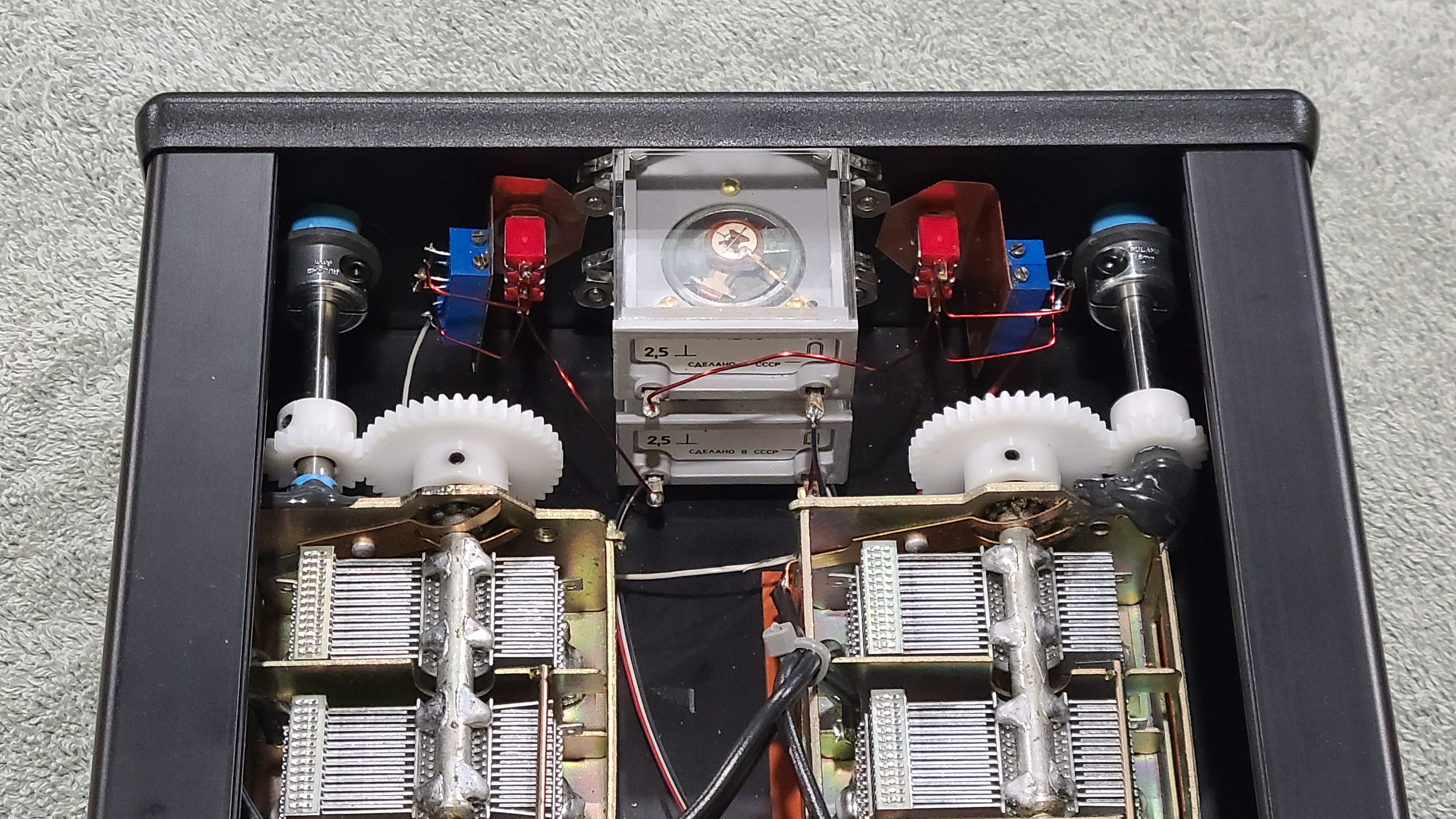
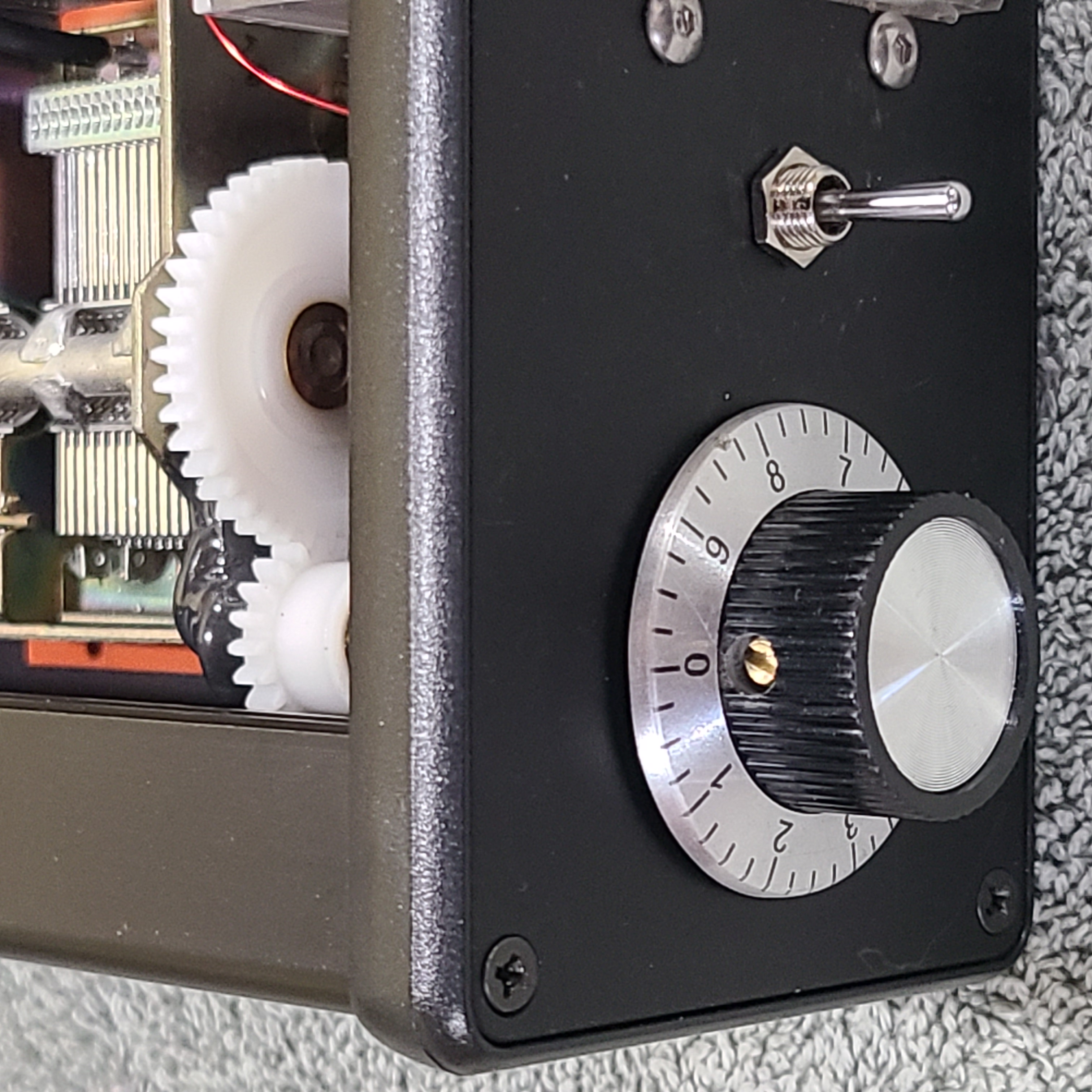
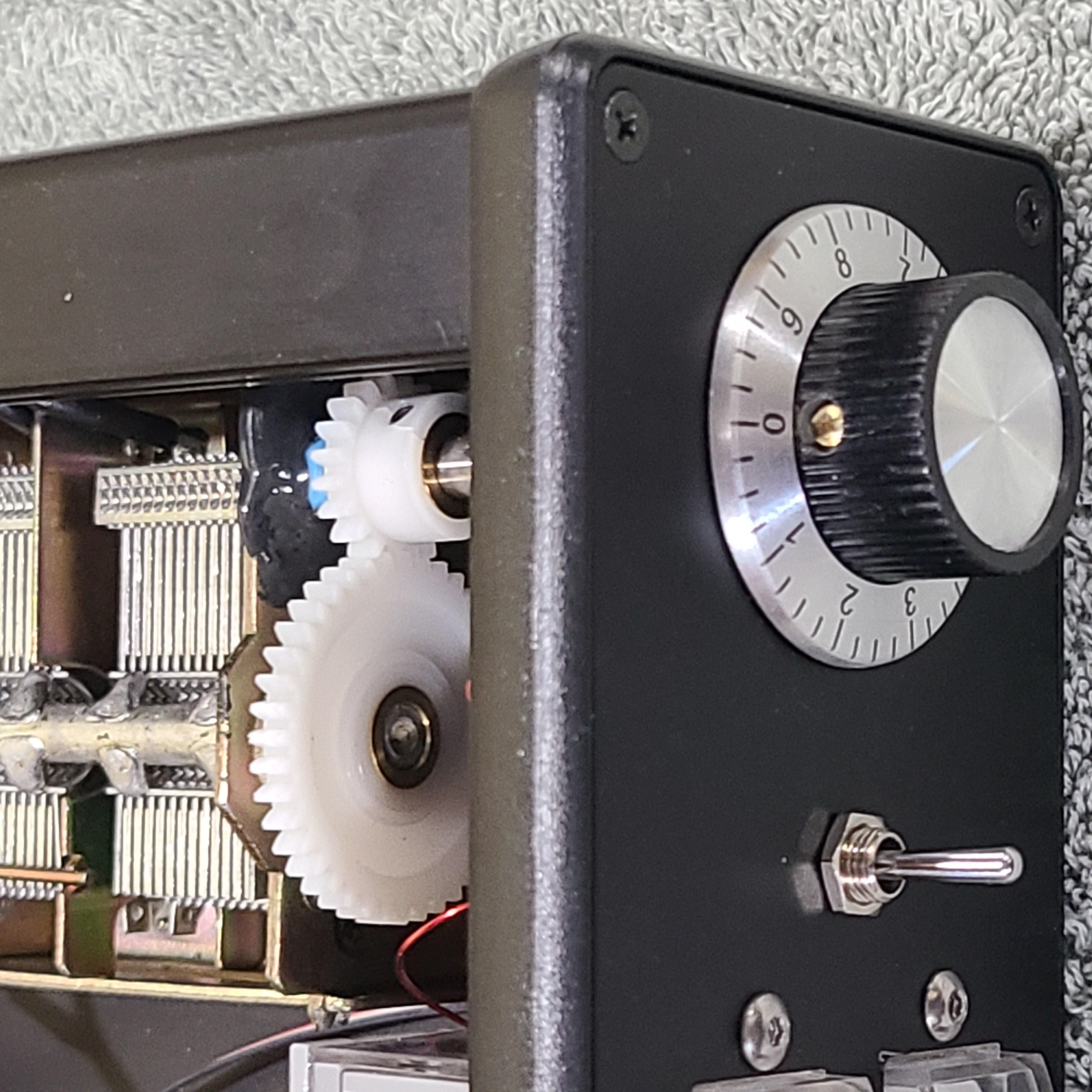
So that the dials might be effective through a full turn, I employed 2:1 reduction gearing for each capacitor. Each drive gear is fixed to a shaft which itself is held captive between two step washers, one epoxied onto the capacitor body, the other captive against the inside front panel by a shaft clamp.
|
|
To plan out gear and shaft placement, first I had to build a model of the Russian variable capacitors purchased from eBay. Models for the gears, shafts, and bushings I simply downloaded from vendors.
|
|
|
|
|
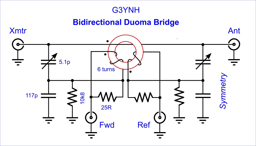
For myself, I chose a Duoma Bridge design as found published on-line by David W. Knight, G3YNH.
|
|
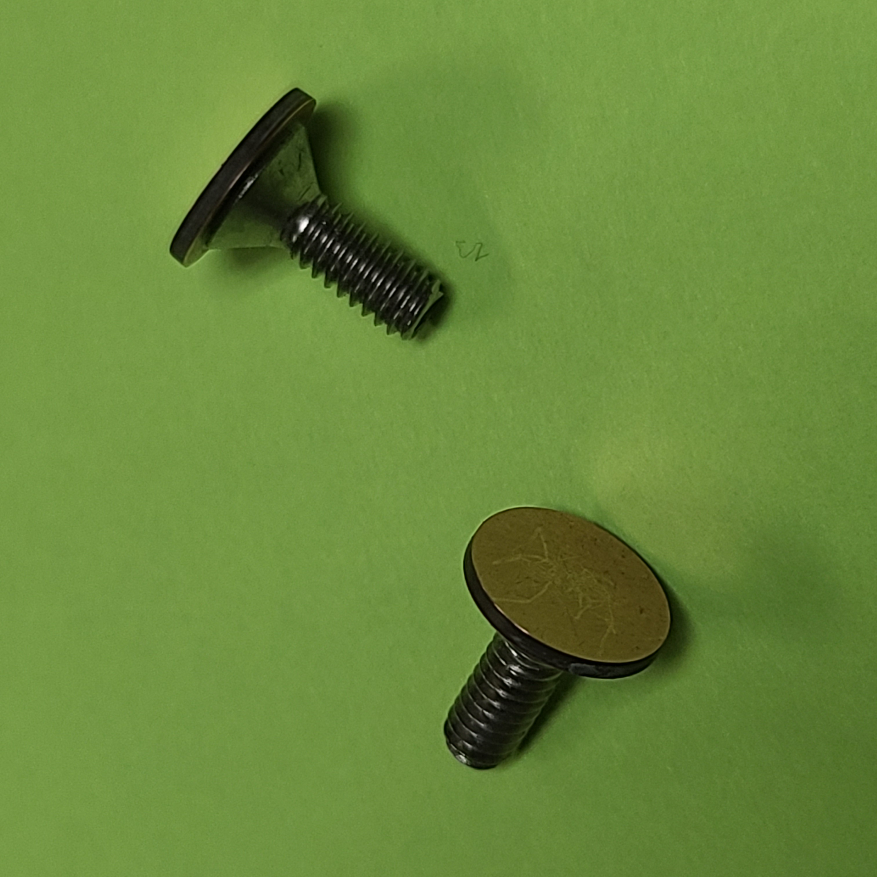
The Duoma Bridge is a very superior design employing an RF voltage divider. Thus two identical, high-voltage caps are required, one for each side along with trimmers. I made my own by spinning cut sections of double-sided circuit board against a belt sander.
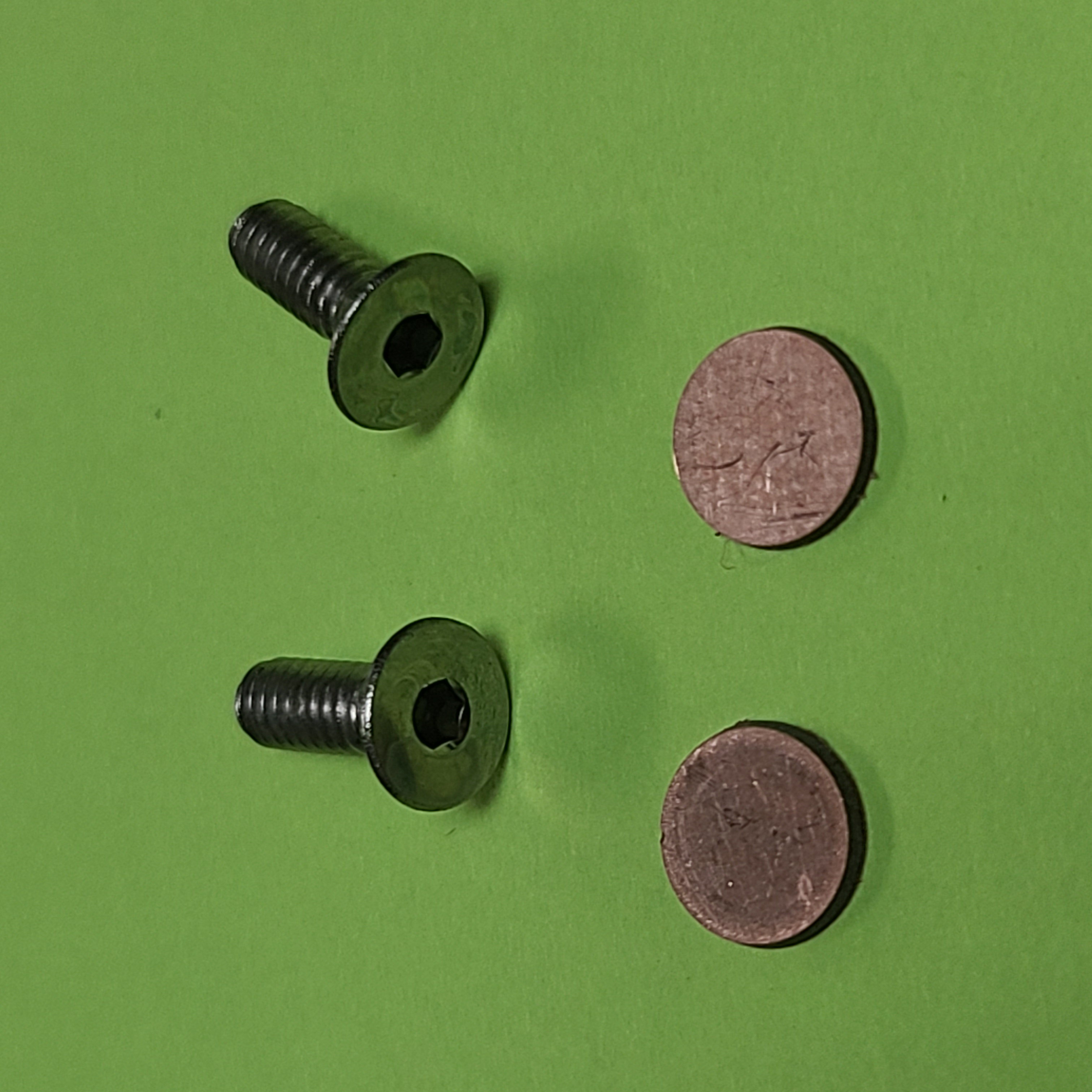
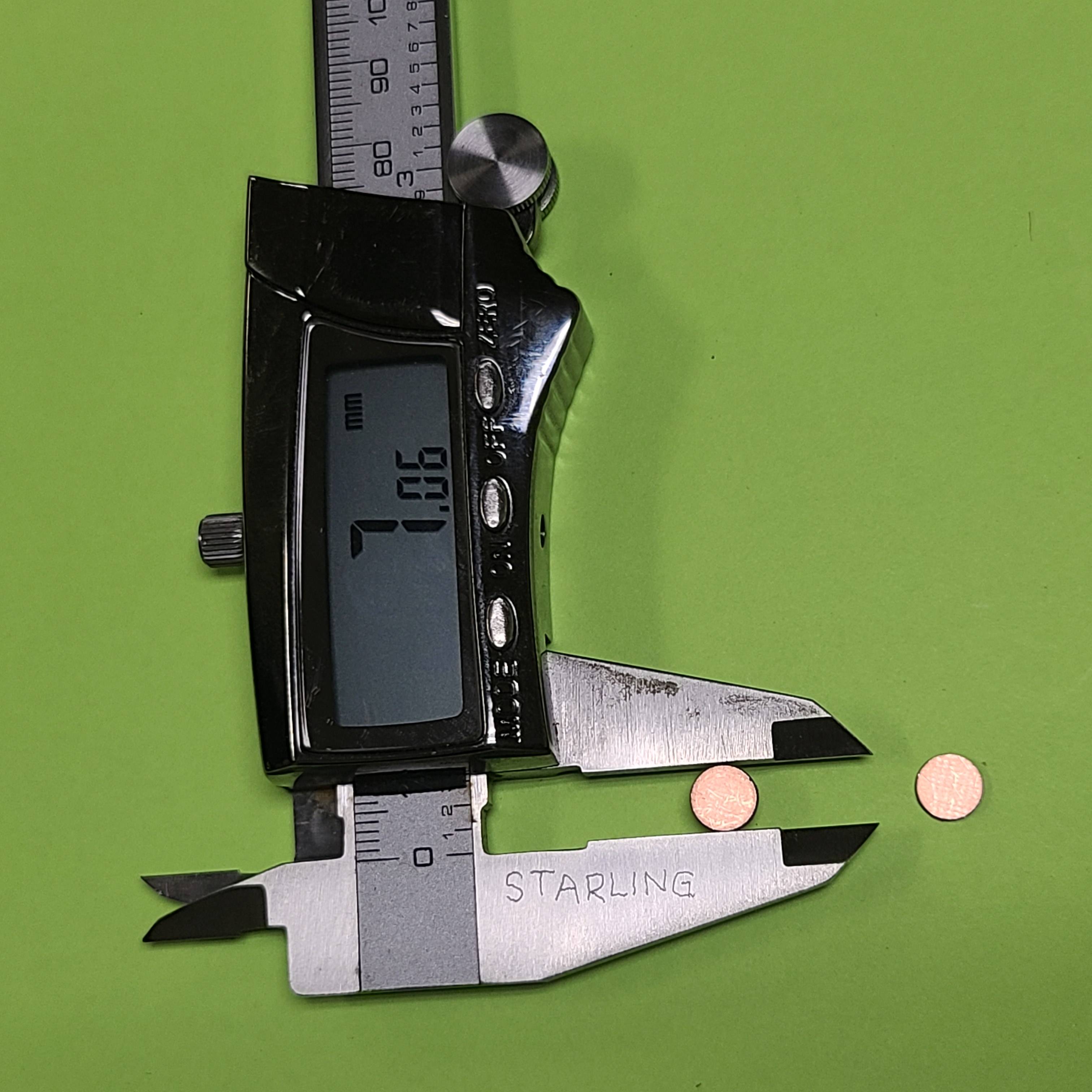
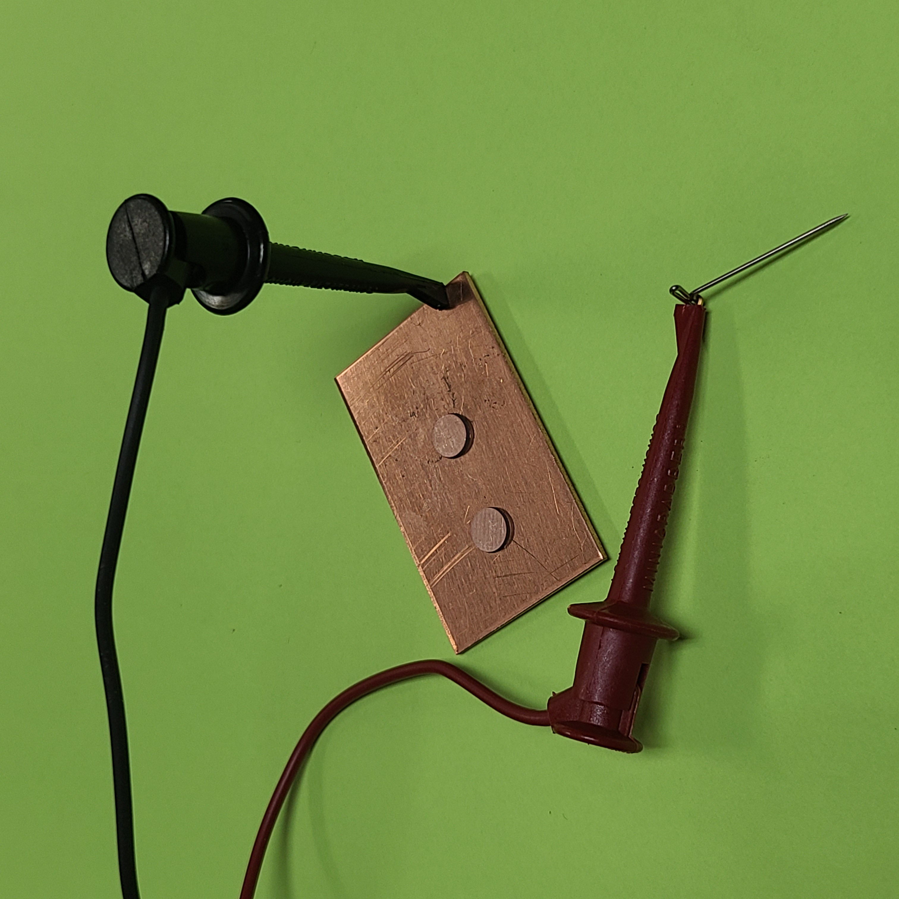
Effecively, this is like turning them on a lathe. First you glue rough-sawn sections onto small, flat-head screws. Then gripping the threaded ends into the chuck of a Dremel tool, incrementally sand their diameters down to exactly equal.
A bit of ex-post-facto trim-sanding might prove needful. This because equal diameters gets you very close but not quite exact. Go for exactly equal measured capacitance.
|
|
|
|
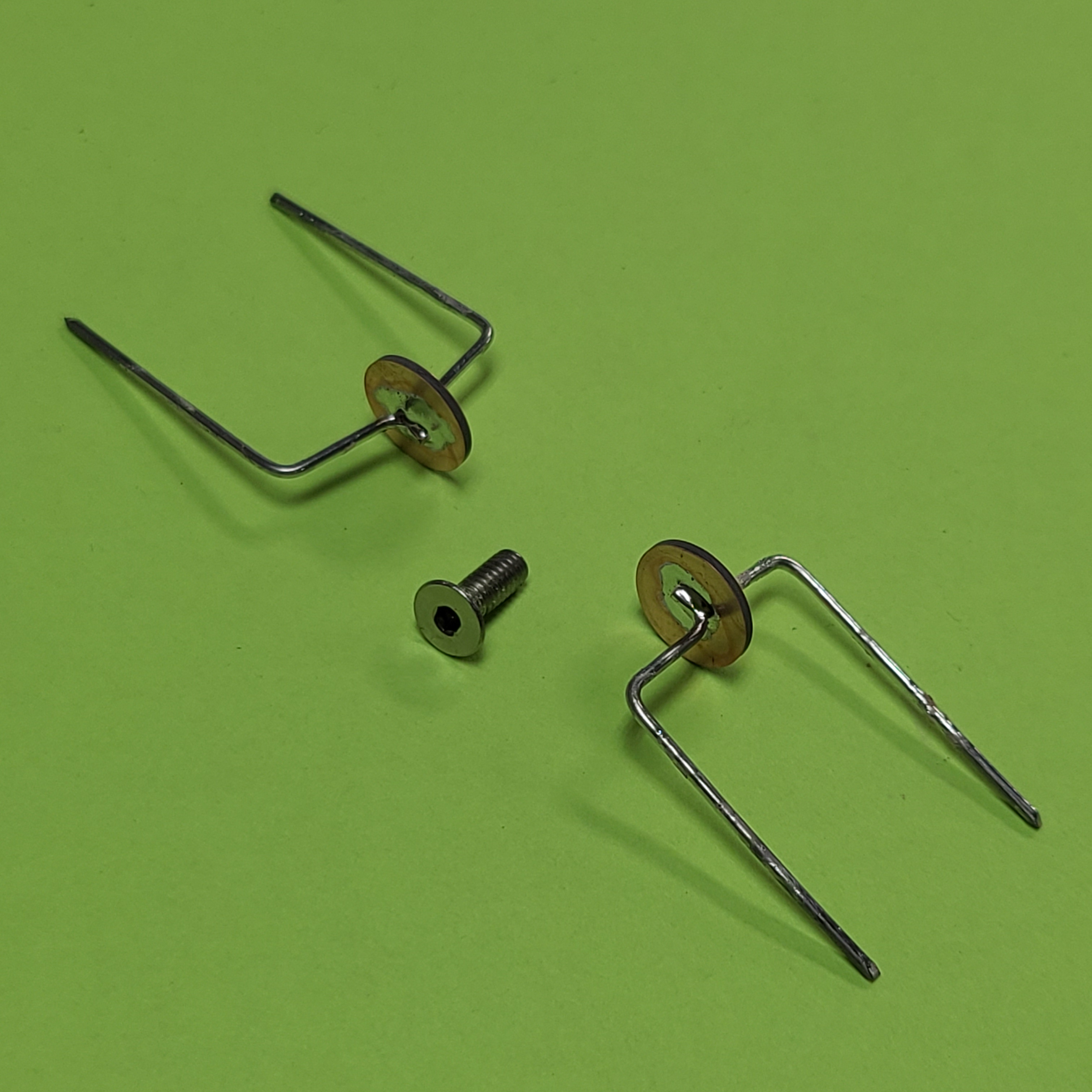
Identical values were assured by LCR meter. After which, I soldered on legs.
|
|
|
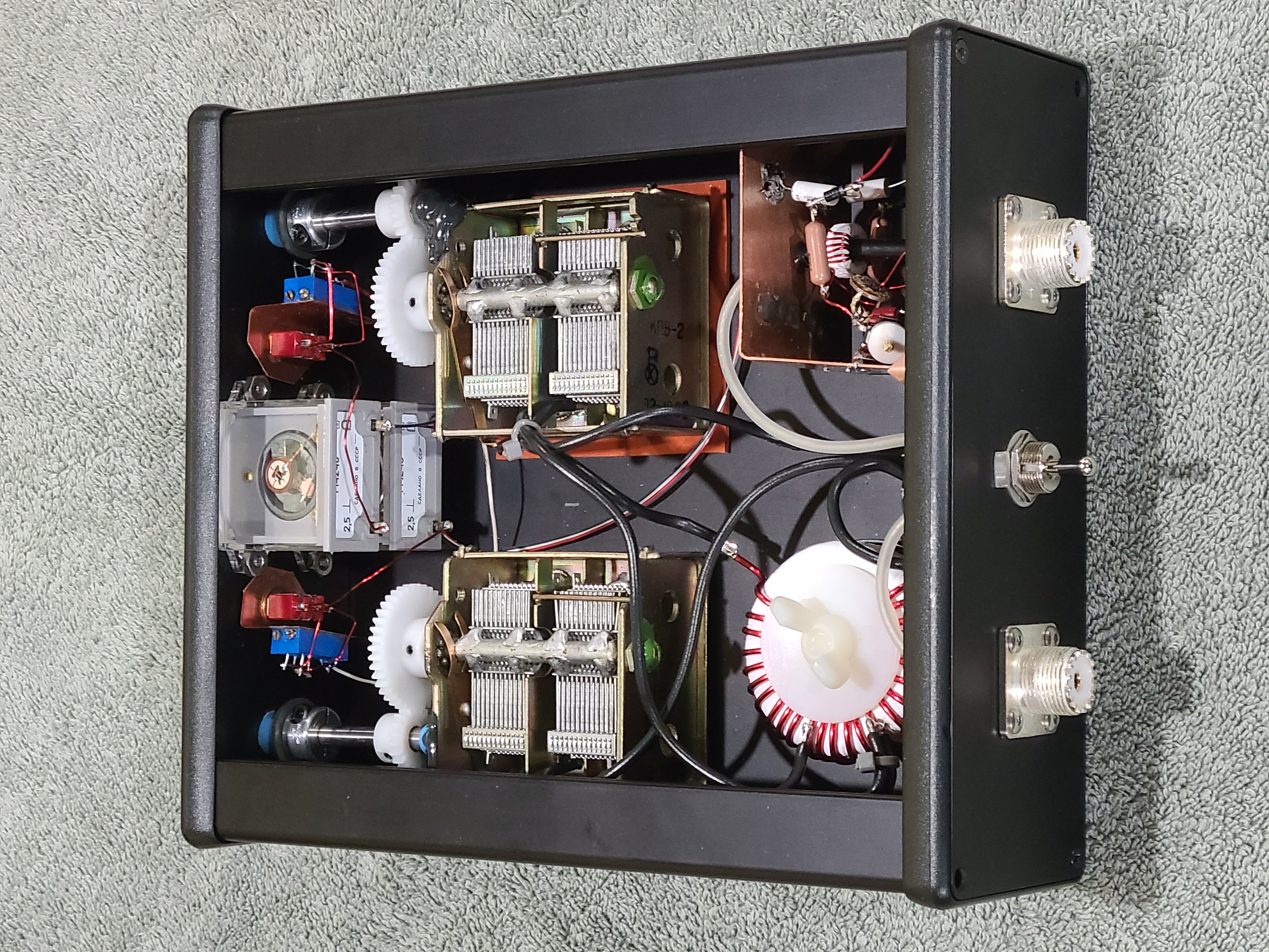
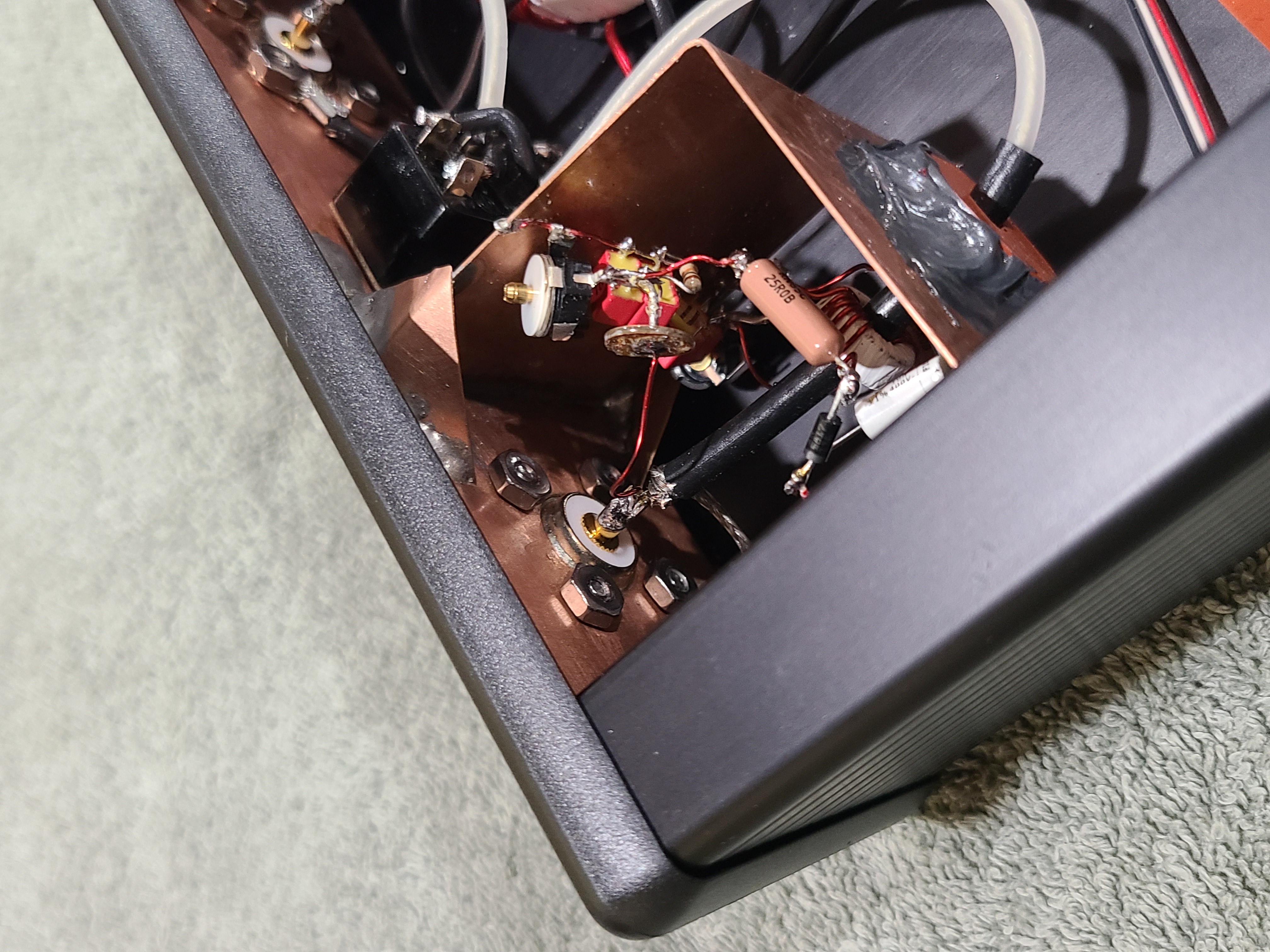
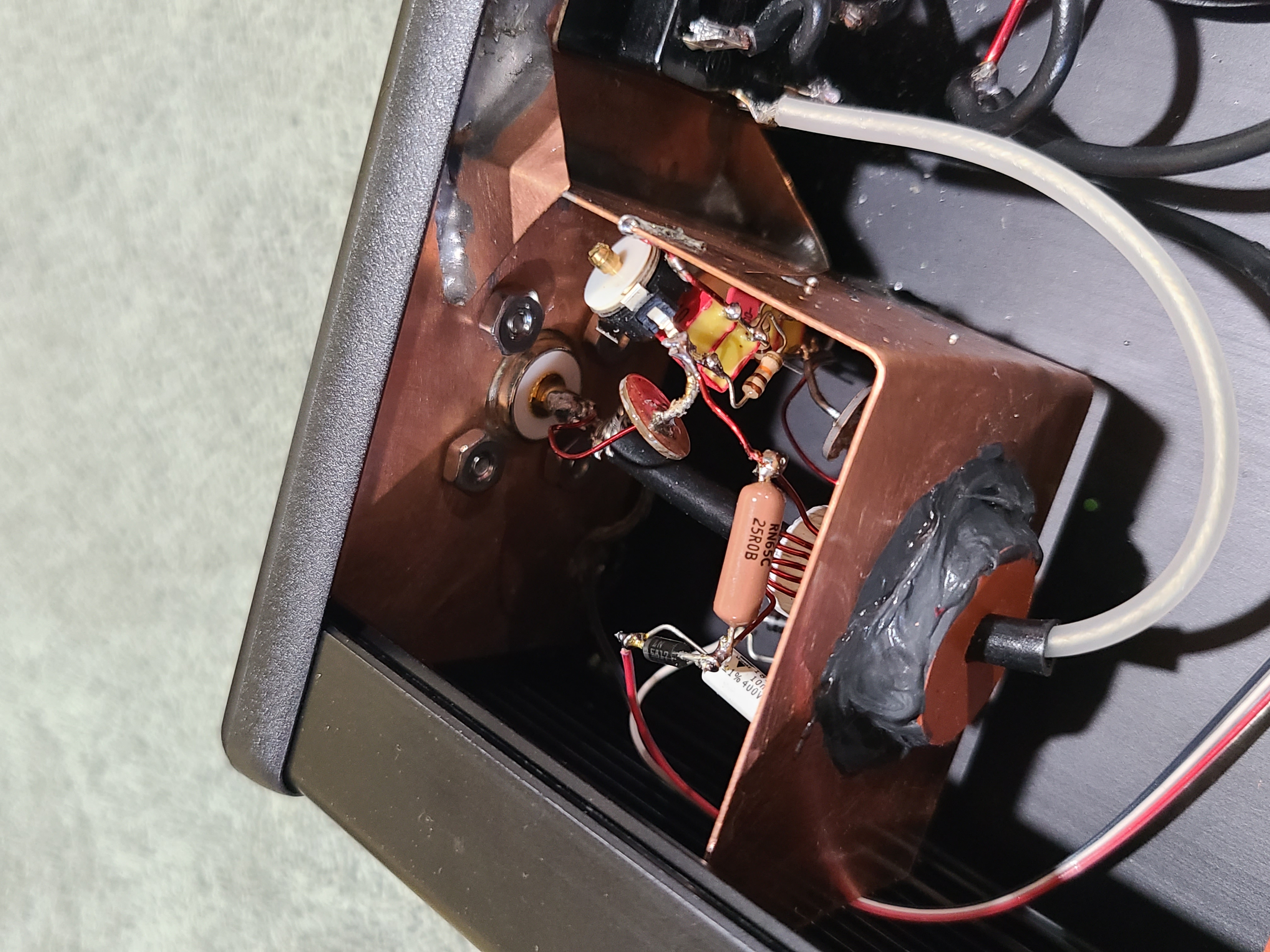
Below are two views of the SWR bridge inside the case.
|
|
|
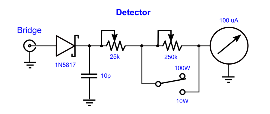
I went with separate meters for FWD and REF. Only Russian units got from eBay met my size and shape preference. The detector circuit’s input RC components I located inside the SWR bridge’s shielded sub-compartment, placing only the potentiometers and switches near the meter momvents. Note them in photos further up.
|
|
Since authoring this how-to back in 2022, I’ve had to remove the two most excellent reference links.
F. H. V. Geerligs, PA0FRI Designer of the original FRI-Match. It was his own instructions that I followed in building my own in 2023. His QRZ page remains, but his website of plural such projects no longer does.
David W. Knight, G3YNH Author of the accurate coil inductance formula now used everywhere. I learned of David’s SK status from his wife. She actually apologized for the loss of David’s most wonderful website, chock full of technical info, explaining that the ISP host had deleted it for non-payment without the family realizing. And for lack of his login password, efforts to recover it had all failed. A lesson for us all.
Latin for “Let the moocher beware”. I built this for me, and used it with glee. I share the plans with you for free, but offered without even so much as the smell of a dead warranty (or wheriot, as the case may be). Whatsoever disasters of cosmic proportion as may result from the use of these plans, any and all culpability rests wholly and solely with the user.