Main Tab
A free, open-source calculator for solving DC-passing L Networks.
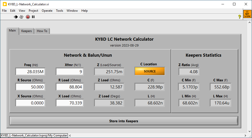
Calculates in a free-running loop. Start it, then change any value to instantly get new results. Try out and store plural solutions. Make small changes by clicking next to a digit and using your keyboard’s up/down arrow keys. Full examples for all nine HF bands on three separate antennas herein detailed.
|
|
|
|
p, n, u, m, k, M.
C at source or load side of L?RSource = RLoad but XSource != XLoad.
ZSource < ZLoad, that being the oft-read rule-of-thumb.I am wanting an all-band antenna for portable use. I want it to be my own design. Below are the three I shall try out first. All are non-resonant (aka "random wire") antennas. As such they’ll start out already somewhat inefficient. An L-Match (unlike a T-Match) will not further worsen that inefficiency. An L-Match, for having one less major component, is 33% more portable than a T-Match. Hence this calculator.
The first thing to know in designing an L-Match, is what are the impedances I shall expect for it to transform. Below are the criteria which I have feed into my antenna analysis software of choice.
For each, antenna, there will be a different complex impedance on every band. And few indeed are the rigs having built-in antenna tuners so widely capable. My own is a Mission RGO One. Its built-in antenna tuner, when augmented by my homebrew FRI-Match manual tuner has served me admirably on plural occasions for bringing an 11.29m doublet to heel. This no matter the angle or orientation of wires. Nor yet the height above ground. No matter either, whether coupled by 9:1 balun or unun.
Even so, still I’d been thinking to homebrew an L-Match since even before building the FRI-Match. Very hopefully an L-Match might suit my other two rigs: an IC-745, and a QCX+ with matching 50W amp. Neither of those have built-in tuners.
Hence this present calculator. I now may determine the minimum ranges of L and C to be required. This with assurance of my choice suiting at least two lengths of random wire: 11.29m and 22.68m. Just possibly also a 36.07m length?
Step one is obtaing Rin and Xin values for each band on each length of wire. This as predicted by some variant of antenna simulation software. While owning the whole shebang of free softwares (4NEC2, EZNEC, Nec2Go, and MANAGAAL), at present I am enamored with a non-free one: AN-SOF Link .
Having got from AN-SOF an entire table of Rin and Xin at chosen frequencies, I feed them by sets into my calculator. No need of writing down. For each I press the Keep Values button. Once all have been kept, I switch to the Keepers tab, then copy-and-paste somewhere permanent.
I now have an entire list of the resultant L and C values which the L-Match I am to build must accomodate. Specific examples follow below.
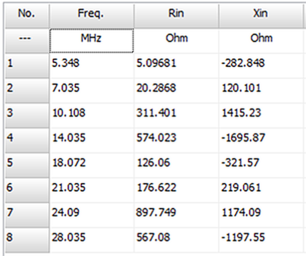
This is the antenna I cut specifically for portable use while in Vancouver and on Pender Island (Ref: QRZ ). I cut it based on math only, subjecting the doublet only to the meagerest possible testing prior to departure. Ex-post-facto, I now analyze it properly. From AN-SOF, I obtain a Results table. Below I show it in partial screenshot.
|
|
Extracting the values for Freq, Rload, and Xload, I feed these into my brand-new calculator, obtaining a table of keeper values, as below. Of principal interest are just only the columns for Henries and Farads. Mainly the max and min of each. Those for sizing components.
Of secondary interest is the progression of spans between Farad values. Those for deciding upon whether to use a roller or a tapped inductor. If the latter, how many taps needed.
   Freq    R-Src    X-Src   R-Load   X-Load   Z-Load   Z-Degs  Z-Ratio  Henries   Farads  Cap Loc
3.5250M   50.000   0.0000   2.9549  -831.21   831.22  -89.796   16.624  38.062u  3.6031n     Load
5.3480M   50.000   0.0000   16.708  -278.76   279.26  -86.570   5.5852  8.9977u  840.17p     Load
7.0350M   50.000   0.0000   57.291   125.36   137.83   65.439   2.7567  2.6845u  311.19p     Load
10.108M   50.000   0.0000   508.98  1.1888k  1.2932k   66.822   25.864  6.3332u  49.743p     Load
14.035M   50.000   0.0000   970.44 -1.8899k  2.1245k  -62.820   42.490  5.4390u  18.640p     Load
18.072M   50.000   0.0000   105.26  -376.47   390.91  -74.379   7.8182  2.3315u  10.424p     Load
21.035M   50.000   0.0000   114.73   199.64   230.26   60.114   4.6051  1.0861u  75.496p     Load
24.090M   50.000   0.0000   781.84  1.4225k  1.6232k   61.205   32.464  2.6917u  19.542p     Load
28.035M   50.000   0.0000   485.42 -1.1932k  1.2882k  -67.863   25.764  2.3299u  9.5484p     Load
From the above, 80m looks unfeasable, unless in my L-Match I switch in a rather large fixed capacitor in parallel to the 0.22-1060pF 900V air-variable (Oren Elliott Products 73-1-30-55T) which I have on hand from EBay.
If wanting only 60m and up from this antenna, then I need only to wind a minimum 10uH, multi-tap toroid for the inductor. Not only that, I have a fair idea how many ratiometrically located taps it shall require. For which latter solution, I have yet another calculator in LabVIEW: link
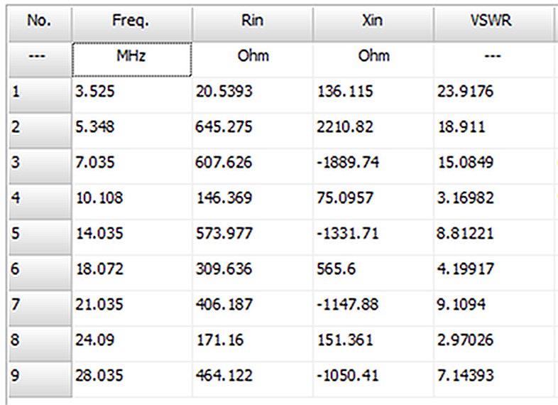
Now let us try a longer non-resonant length. Below is the AN-SOF analysis report.
|
|
  Freq    R-Src    X-Src   R-Load   X-Load   Z-Load   Z-Degs  Z-Ratio  Henries   Farads  Cap Loc
3.5250M   50.000   0.0000   20.539   136.12   137.66   81.419   2.7531  9.4308u  528.77p     Load
5.3480M   50.000   0.0000   645.27  2.2108k  2.3031k   73.729   46.061  19.021u  58.683p     Load
7.0350M   50.000   0.0000   607.63 -1.8897k  1.9850k  -72.175   39.701  12.832u  28.727p     Load
10.108M   50.000   0.0000   146.37   75.096   164.51   27.160   3.2902  1.2931u  183.57p     Load
14.035M   50.000   0.0000   573.98 -1.3317k  1.4501k  -66.684   29.003  4.8203u  19.132p     Load
18.072M   50.000   0.0000   309.64   565.60   644.81   61.302   12.896  2.2391u  45.329p     Load
21.035M   50.000   0.0000   406.19 -1.1479k  1.2176k  -70.513   24.353  3.2101u  11.731p     Load
24.090M   50.000   0.0000   171.16   151.36   228.49   41.487   4.5697  746.02n  68.072p     Load
28.035M   50.000   0.0000   464.12 -1.0504k  1.1484k  -66.162   22.968  2.1209u  10.407p     Load
This twice-longer non-resonant wire does very much better on 60m. It also allows for 80m. Only the lower half of my 0.22-1060pF air-vairable capacitor will see any use. And further, a homebrew L-Match should maybe include multi-tap air-core inductor to be accomodating the 30m and 12m bands. All facts very good to know before I build.
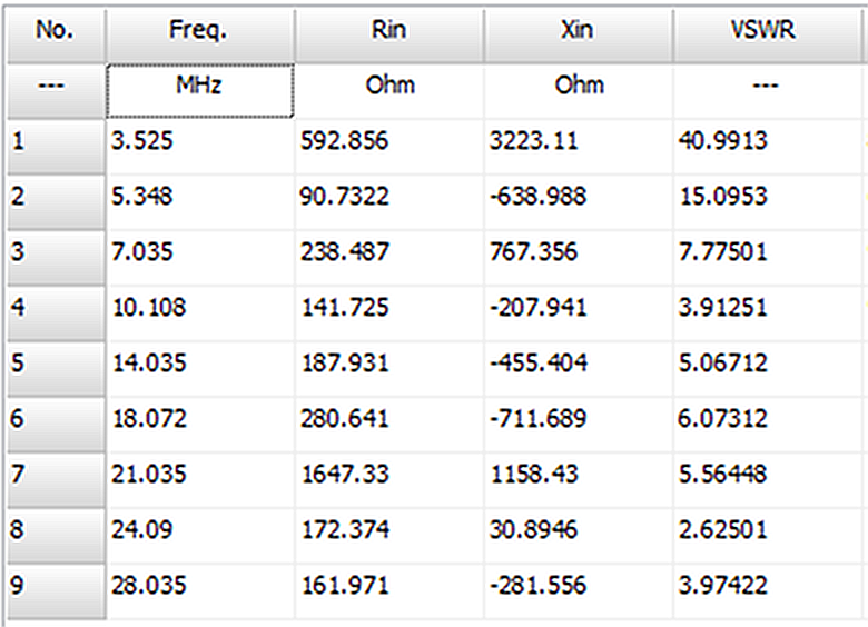
And now for a length probably best suited for staying home.
|
|
Feeding its columns for Freq, Rin, and Xin into my calculator, we obtain...
   Freq    R-Src    X-Src   R-Load   X-Load   Z-Load   Z-Degs  Z-Ratio  Henries   Farads  Cap Loc
3.5250M   50.000   0.0000   892.86  3.2231k  3.3445k   74.516   66.890  35.663u  69.943p     Load
5.3480M   50.000   0.0000   90.732  -638.99   645.40  -81.918   12.908  14.180u  16.123p     Load
7.0350M   50.000   0.0000   238.49   767.36   803.56   72.735   16.071  8.2467u  87.802p     Load
10.108M   50.000   0.0000   141.72  -207.94   251.65  -55.723   5.0329  2.2179u  47.571p     Load
14.035M   50.000   0.0000   187.93  -455.40   492.66  -67.576   9.8531  2.8253u  22.475p     Load
18.072M   50.000   0.0000   280.64  -711.69   765.02  -68.479   15.300  2.8095u  16.235p     Load
21.035M   50.000   0.0000  1.6473k  1.1584k  2.0139k   35.116   40.277  2.6275u  23.506p     Load
24.090M   50.000   0.0000   172.37   30.895   175.12   10.161   3.5024  528.35n  66.051p     Load
28.035M   50.000   0.0000   161.97  -281.56   324.82  -60.089   6.4964  984.44n  15.076p     Load
For ease of tuning the 12m band, I’ll likely be wanting that air-core inductor. A 72.14m doublet being awfuly large for portable use, this one will likely just remain theory.
Common practice is to employ a toroid 9:1 balun or unun (sometimes instead a binocular 5:1 type). But as we have seen from above, neither 9:1 nor 5:1 looks too very appropriate for many cases.
These circumstances being the case, you are entitled to wonder what impelled me to choose such lengths as 11.29m, 22.68m, and 36.07m in the first place. I did have a reason. Each length is smack in the middle of a very wide non-resonant section. Each is very far distant from the nearest resonant length. Like so for all nine HF bands. Even out to the 6th harmonic for each band individually. Cutting is non-critical, nor is mild wire stretch cause for worry.
The sections below point to no single transformer ratio equally suitable for all bands..
Here the 9-band average Z-load/Z-source ratio is 18.2:1. That with a high of 42.5:1 on 20m, and a low of 2.8:1 on 40m.
Here the 9-band average Z-load/Z-source ratio is 20.6:1. That with a high of 46.1:1 on 60m, and a low of 2.8:1 on 80m.
Here the 9-band average Z-load/Z-source ratio is 19.6:1. That with a high of 66:1 on 80m, and a low of 3.5:1 on 12m.
The above would seem to urge toward winding a 16:1 balun or unun, rather than a 9:1. But then there’s the catch of those low Z values, for which a 16:1 turn-down ratio would serve very poorly indeed. Alas and alack. A sensible compromise then, to go with 9:1 or 5:1 ratio despite all.
Another thought, as I have read elsewhere, is to employ a Guanella 1:1 alone by itself. A common-mode choke is hardly to be done with out; and a properly wound Guanella 1:1 makes for the very best.
I myself never wind a voltage balun or unun without I include a Guanella 1:1 on its own toroid in the same package. I do that always, just because. Which practice, of course, means always needing a counterpoise. In which case, why not just build a full doublet? No better way to keep RF out of the shack. Why risk the annoyance, not to mention an RF burn?
A doublet can become a vertical or inverted L simply by swapping balun for unun and running the ground-connected wire out horizontal. I have done it both ways, with equal success. Nothing so good as I have at home, but eminently portable.
The above three cases serve to explain why many an on-line how-to for building an L-Match target only one or two bands. A capacitor large enough to provide the maximum pF needed might equally call for a 6:1 or even 10:1 planetary reducer and turns counter, else tuning would be insufferably coarse down near the very bottom. Alternately, one might employ a smaller range, fine-tuning capacitor in parallel. Or go with just only a small range variable plus also a bank of shuntable silver-mica caps in parallel.
Likewise the inductor. Employ a toroid with 20-plus taps? A toroid in series with a small air-core? Ten-plus taps on that as well? I have purchased (again from EBay) a 4-deck, 20-pos switch whose deck diameter matches closely a T240 ferrite core.
The deadline for my own project is not until next January, though. A return to Simon’s Town, South Africa. This time with my RGO One, non-resonant wires, plus also a kite. I could, very probably, make do with the Fri-Match. Still, I’m going to build the L-Match. And we shall see which is the better.
Suppose I were to at long last indulge a decade-suppressed ambition for homebrewing a multi-tapped balun of plural ratios? One controlled from inside the shack by DC sent through the coax to solenoid-step a 2-pole, multi-throw switch. Then I’d be wanting to know which ratios worked best.
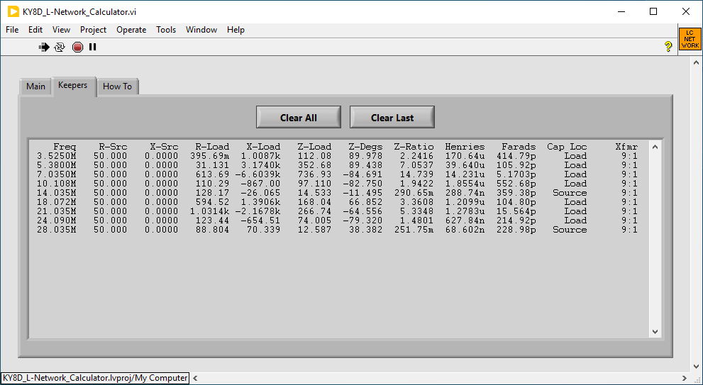
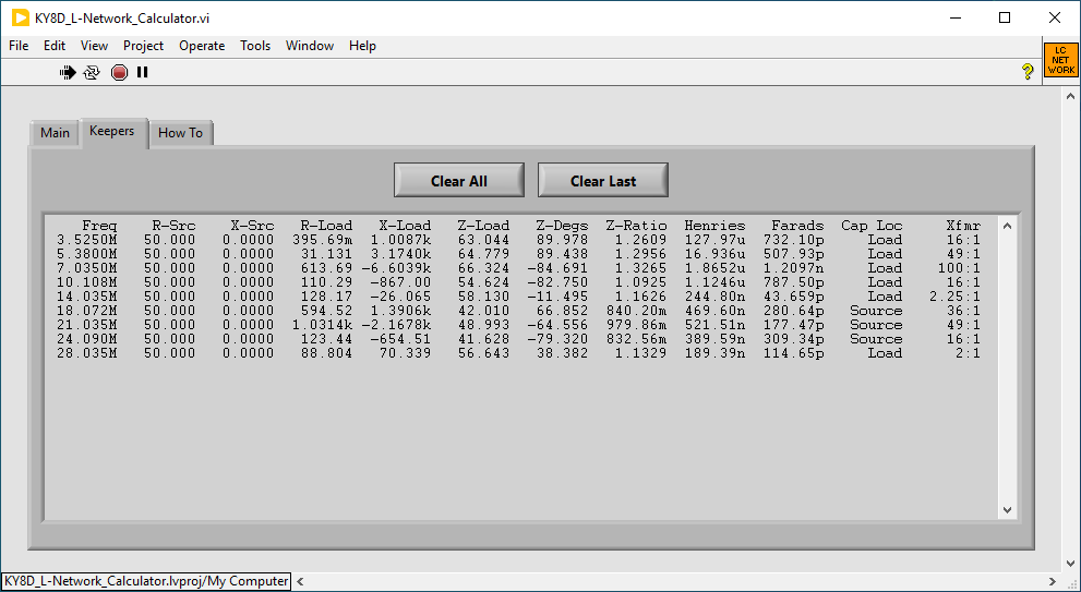
As, for instance, I now show below. For each frequency band, I have adjusted the Xfmr input, obtaining just such a list.
|
|
You’ll need two things for it to run: my *.exe application itself, plus also the interpreter program on which it runs. Kind of like Java that way, except that the Java interpreter is probably pre-installed on your system. The LabVIEW run-time engine will not be.
ky8d.net/free where I give download instructions.*.exe file. Employ a stand-alone ZIP archive software (like 7-Zip ) for the extraction.Many thanks to Jason Le Leivre, whose own website ( link ) I blatantly pilliaged of its JavaScript as an example to study.