A free, open-source calculator to use as an aid in selecting
ring, planet, and sun gears from catalogs such as SDP/SI, KHK, etc.
I searched on-line, but did not find, a calculator to quite suit my need. I wanted one that gave full dimensions down to at least four decimal points. Very helpful would be if might show plural solutions all at once. And most importantly of all, it should be lively and quick, with no tedius Calculate button needing to be re-clicked over and over. Needless to say, I couldn't find one like that. And so, I wrote my own.
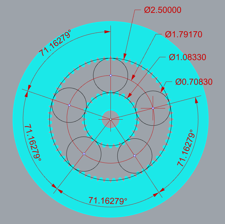
Above is a shrunk-down screenshot (made pretty in GIMP) from Rhino 6 CAD, showing example output values generated by my calculator. Black circles are the Pitch Diameters: ring, planet, and sun. Why model teeth when there's no need? Feel free to click on it if preferring to view an un-retouched screenshot. Compare the numerics you see above with those you get by entering the values below into my calculator.
| Value | Numerics |
|---|---|
| Ring Pitch Diameter | 2.5000 |
| Planet Pitch Diameter | 0.7083 |
| Tooth Pitch | 24 |
| Planet Count | 5 |
Maybe at some point I'll get around to repeating that proof in Solidworks also. Possibly not, since at work they've announced doing away with Solidworks company-wide in favor of Creo. So later on maybe Creo instead. But seeing as how I have maintained a personal license for Rhinoceros 3D CAD ever since version 4, and have always been very happy with it, why pay more? Very espcially, why pay an annual fee?
As all the math here is in terms of ratios, the unit of measure should not really matter. Except that it does, because of how gear pitch is stipulated. So then, just do like so...
It's text entry box for pitch in the Teeth panel. Like that so LabVIEW can parse the entry looking for a decimal point. Seeing a decimal point, it will invert the numeric value (teeth-per-unit → units-per-tooth). Having done that, the user is put on notice by a change of both color and text in at the very top of said gear set's main panels. It might seem absurd to have 4-decimal accuracy for milimeters, true. But why downgrade just for appearance's sake?
There are two websites in particular which I drew upon for information to build my calculator.
Above are three thumbnails. The two on right jus show the same image bigger. The left-end thumbnail is only partial; clicking on it will provide much more info.
The image Panel 1, once clicked on so as to have all the info, gives dimensions in inches for an example gear set, with one of those dimensions in red. Firstly lets look at the gears.
That said, however, some pitfalls exist. You might expect that, there being five gears, their angular separation would be a precise, natural, and obvious 72 degrees. It isn't however. Because of the gear teeth needing to mesh, the placement is just a bit off from that. Instead it works out to 71.16279 degrees between planet gears 1, 2, 3, and 4, and 75.34884 degrees between planet gears 1 and 5.
Other than that very minor issue, the gear set does work. So to call your attention to the issue, my calculator shows the angle in red. You can choose not to use it on that account. But since it would work, I chose not to exclude it. Thus for angular separation of planets, shy away from the red. But do wince slightly and use it if for some reason you must.
Another reason to be shy of red angles is this. Above, in cyan, is shown where I have downloaded 3D models of commercial gears from the SPD/SI online catalog. The ring and sun only. No model to be got for the 17-tooth planet gear because SPD/SI does not sell them. Nor does KHK. Probably nobody does. It seems no one makes them.
Thus have I learned that while the above combination of values (ring/planet/sun = 60/17/26) works out just fine in theory, and despite having been able to replicate it on that wonderfully clever animated website linked-to above, I have run into one of those cases where pure math stands in defiance of the commerical market. The catalog for SPD/SI lists available tooth counts which run like so: 7, 8, 9, 10, 11, 12, 13, 14, 15, 16, 17, 18, 19, 20, 21, 22, 23, 24, 25, 26, 27, 28, 29, and 30. With the missing values shown here in red.
At counts above 30, gaps in the sequence become increasingly frequent. So having the catalog open can save quite a lot of frustration. And having a free-running calculator with no Submit or Calculate button helps out with reducing frustration. Which is why I wrote it. I trembled at the thought of having to put up with that annoyance again, and made my own tool for getting around it. Short-term memory issues, you see. Which is why my lovely wife Karin chooses all our airline tickets.
The above limitation on gear availability is, of course, only for buying gears from a supplier. With 3D printing, we can all be our own suppliers. For Rhino 6 CAD, there's a free script named GearGen for desigining gears. All I had to do was download, unzip, and install it. Easy peasy.
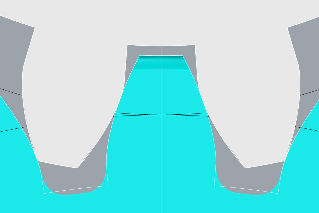
Not that I don't find a wee little fault. In the thumbnail above, cyan represents the commercially purchaseble ring and sun gears (downloaded as *.igs files), while white is from the GearGen script loaded into Rhinoceros. A white outline following the cyan colored gear is the result of GearGen,as well. Were I to extrude and cap it, then I'd have a 3D-printable substitute for the expensive commercial sun gear.
Now, click on the thumbnail for a zoom-in. See where on the cyan gear the inside of each tooth has a fillet? That's really good for preventing fatigue. The white outline lacks that, having a sharp inside corner instead. Sharp corners are stress risers. Stress risers are where cracks always start. And once they start... See them on the solid white planet gear also? Very bad form, from my point of view. I can say that from the perspective of having worked fifteen years in automotive fatigue and durability.
So what I will be doing, come the day I need to design my own gear, is happily thank GearGen for generating an otherwise very nice set of teeth, but then, before extruding the curve to a solid, I will manually add a generous fillet to each and every one of those sharp inside corners. The gear will last a lot longer that way.
|
|
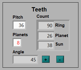
Only the right image above is a thumbnail. Click on it to see bigger, if you want. As for the image at left, however, note that this time the angle value is both reasonable seeming and also black. Instead it is the planet count which shows in red. And whenever that is the case, the gear set will not work at all.
Why won't it work? The planet diameters are just slightly too big. The teeth of each, although fine for the ring and sun gears both, each planet will gnash teeth with its neighbor.
Squint at the image on right and you'll see that there is not quite enough space to be having eight planets instead of four. I would have liked to make it show that, except that the visualiztion website does not allow more than five planets.
And so, to recap, be cautiously shy of planet angles red, and never employ a red planet count.
While you could use this calculator as an aid to designing gears from scratch, my intended purpose is that it should serve as an aid to help select gear sets from on-line catalogs. So here's how to suffer minimum possible frustration.
Only one of these to my knowledge, and it is minor. Use of the [+] and [-] buttons for inc/dec-rementing planet-gear tooth count by single digits will sometimes get caught betweeen two disallowed values. They'll still try to work, but a built-in limit will knock them back. If currently between two such disallowed tooth counts, then they will appear to be stuck, caught between two invisible walls. The thing to do then, is click instead into the planet gear's Pitch Diameter wiget, and make an adjustmet there.
Where it might also happen that you seem to hit the same snag. The reason for this is that you are attempting to make too small an adjustment. Be mindful that widget having four decimal places of accuracy. So if using the up/down arrows on the rightmost digit, it might not be enough to get one more tooth. When that happens, try one digit to the left. Or two digits, even. How much you will need depends on the gear pitch.
You’ll need two things for it to run: my *.exe application itself, plus also the interpreter program on which it runs. Kind of like Java that way, except that the Java interpreter is probably pre-installed on your system. The LabVIEW run-time engine will not be.
ky8d.net/free where I give download instructions. ZIP archive software (like 7-Zip ) for extracting the *.exe file to somplace useful prior to trying to run it. Otherwise, Windows will issue dire warnings of an unrecognized app. Once extracted from out of its ZIP archive, however, Windows will know to pass it off to the LabVIEW Run-Time Engine instead.