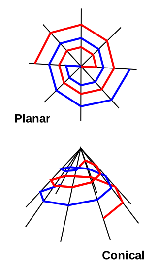
Design planar or conical spiral antennas for HF, exporting your designs in three formats: *.nec, *.ant and *.txt. The latter is text macro data for importing into the 3D CAD platform Rhinoceros.
During a QSO, when other ops describe their own station, always it’s more fun to be given a little surprise. More fun yet when it can be I who delivers the little surprise. QSOs that might have been hit-and-run can be extended into proper ragchews.
Surprising indeed would be a log spiral built to HF proportions. Even my 2.5-acre rural parcel, only two locations exist where I might cram in a conical spiral. This on account of so many trees. I can think of several, however, where a vertically oriented planar spiral could be slipped in on the skinny. No way to find out until after I’ve modeled a few.
This calculator I had figured to just bang out, quick and easy, in the Perl programming language. Which part of it did go simply enough. Rather it was the data analysis part which ballooned beyond expectation. So here goes with that.
There are two main catetories of spiral antenna: Archimedes and logarithmic. This calculator can do both. If fed a value for 𝜏 (Greek letter tau) of 𝜏 > 1, then 𝜏 will be used as a turn-by-turn spacing multiplier. When 𝜏 <= 1, 𝜏 will instead be employed additively, the unit-of-measure being meters (0.9 = 900mm).
Adding a 3rd dimension, we can obtain conical spirals. Commercial versions of these are in use at coastal stations, installed both point up and point down. My calculator can output both versions.
Bi-conical spirals also exist. I just don’t support those directly quite yet. As a work-around, you could do this. In a 3rd-party program (like Nec2Go, 4NEC2, etc) select one whole spiral arm and rotate it vertically 180°. Either that or mirror one arm vertically, then delete the original.
As for myself, presently I only consider a planar log-spiral, oriented vertically. This so as to have something very broad-band which I might skinny in between trees. A satellite view of KY8D’s QTH reveals open space in my front yard, it is true. But I have different ambitions for a future antenna just there. Being vacant at present, however, I could use that space to lay out a planar spiral antenna of HF dimensions. I picture myself tethering knee-high tomato stakes in a big circle for a couple of days. Then I would build it just like how spiders do, starting with the diagonals. For these, I think it might be best to use braided fishing line. Or, just possibly, 2mm Mastrant guy cord.
Atop these stretched-taut diagonals I'd then lay out the spiral arms. For these, I think, DX Engineering’s 19-strand, 14AWG, UV-safe wire would likely serve best. This brand for being conveniently limp. No worry for any kinks to deal with when comes time to move it upon completion.
As for the feed point, options are plural, depending on my final design. I’ll mull over them further down-page.
The Perl script builds only 2-arm spirals. These from single wires. It can also quasi-fatten those arms by laying geometry such that each leg is outlined as a pair of wires joined at both ends. I had thought that would help more than actually it does. It turns out, however, not worth the cost of twice as much wire.
At costal and NVIS transmitting facilities, opposing arms most generally wind downwards and out from the top of a tower, tethered a points along four or more guy lines.
Alternately, they might wind upwards from the base. It might be two arms mutually opposing as when winding top-down, or it might be a single arm working against radials fanning out on the ground. But as four or more masts are required, I won’t be modeling such as these.
Spiral antennas are very, very wide band.
In theory, a sprial antenna would have no upper limit (were it possible for the feedpoint at center or apex to be infinitesimally small). Best to decide upon a maximum frequency of interest, then (as with an LPDA) multiply that by 1.5 for a modicum of head room. Lambda/2 of this MHz shall then be the spiral’s inside diameter.
For a conical spiral, this amounts to truncating the apex.
Choose any MHz you so please, multiply that by 1.1 (for a bit of foot room), and this becomes the spiral’s outer diameter.
Spirals are fed at their center.
No problem here, just run the coax or open wires straight down the cone’s axis to the ground.
The free-space radiation patterin for planar spirals is your classic figure eight ... perpendicular to the flat of the plane. Polarization is circular. Hence an issue for running the feed line.
At VHF, nearly always the answer is something called an infinite balun. This amounts to nothing but coax, the shield of which is bonded to one leg of the sprial. Thereby does the coax spiral in along with that leg. Upon reaching center, the coax’s center wire connects to the start of the spiral’s opposite arm.
In theory, there is nothing to stop us from doing likeiwse down at HF. It makes for a lot coax, however. Way too much weight. Also far too much surface area during ice storms. I just don’t see myself wanting to try it.
Plus also, so I have been informed (on Facebook, but from a trusted source) that infinite baluns do not transform impedance. They carry high SWR along their whole length.
If staying perpendicular to wires comprising the spiral, one might get away with direct radial routing, the feedline’s two legs on opposite sides of the spiral.
If the above makes for issues, then all that’s left is to be lead away perpendicular to the plane of the spiral. Then at some distance, turn the needed right angle.
In an HF planar spiral having a 50MHz upper boundary there’d be plenty of room for a balun at center. The coax could then radially out from the central diagonal.
Only for conicals, since what this ammounts to is a diagonal wire shorting the far ends of the two spiral arms. I'm thinking this might help some in reducing noise. This because of being closed like a loop for, in effect, having no ends. Untried in the real world, as yet, all I can claim is that it doesn't hurt anything according to results I’ve got from NEC.
No GUI with this one. The script is in Perl. So you need a command-line window. Also to supply the script with arguments for how to proceed. A bare minimum example would be as below...
KY8D_Spiral_Calculator.exe --f_hi 45 --f_lo 13.5 --div 6 --dia 2 --tau 1.05
What that would get you are three files *.nec, *.ant, and *.txt all written to the same directory as wherein the script itself resides. A poly-sided planar spiral of 6 radii having 2mm wire and an expansion factor of 1.05. Useful range would cover 14MHz to 30MHz (and above). At end of its run (barely a second) the script would tell you how long each leg was.
Other parameters are available as below. You can even output plural versions of an antenna, each iteration having a particular parameter varied in steps by a chosen amount.
--f_hi MHz of highest freqeuncy
--f_md MHz named for plotting within the file
--f_lo MHz of lowest frequency
--seg segments per wire (1 < N)
--div divisions of circle ( = 4,6,8,10,12) Default = 6
--tau expansion factor. For N > 1, multiplies by N. For N <= 1, adds N meters.
--hgt m feed point height-above-ground (0.0 <= N)
--dia diameter of wire (0.0 < N) Expects mm. Append "GA" for AWG.
--fat fatten spirals (1 <= N <= 3). Default = 1
--ohm Z Ohms impedance (if different from $ohm)
Two below required for conical only. Defaults = 0 (flat spiral).
--deg degrees for the cone (0 < N <= 60)
--zee m initial spacing in Z (0.0 < N)
--iter output plural files: any arg above.
--0th iter start value.
--nth iter finish value.
--stp iter step value.
--path output file path (c:/foo/bar).
--stub short spiral arms at end (only for conical).
--spin rotate orinentation in-plane by degrees (0 < N < 360)
--flip flip orientation to vertical (only for planar).
--help show this info
I freely share all my own results. Here all all my trial designs performed in pursuit of a future antenna for my own QTH. Step-by-step I narrow the parameters down. Plots by the dozen for azimuth gain, elevation angle, and SWR.
Here I work towards a broad-band design to fit on the skinny in between random groupings of trees on my lot. Step-by-step I narrow down each parameter. Weighing trade-offs, I make my choices.
LINK ☜ Ranges of Tau: Trying out a range of spiral-expansion ratios. Weighing the balance between performance and wire-length economy.
LINK ☜ Segmented Curves: Trying out quasi-spirals of differeing resolutions. Smooth-curve spirals approximated by staight lines: from 6 to 16 per full turn in increments of 2. Seeking the balance between performance and structure complexity.
LINK ☜ In-Plane Rotations: Trying out a range of spin orientations: from 0° to 175° in increnements of 5°. Exploring the relationship to ground on each of five HF bands.
LINK ☜ Smaller ODs: Setting div = 32 to minimize aliasing, I explore the result of reducing OD to lambda/2 from 13.5MHz to 17.3MHz. Sacrificing some performance on 20m in trade for improvment on the 17m and 12m WARC bands, with like benefit to 15m as well.
LINK ☜ Coarser Spirals: Now to find out if construction will be practical. Therefor setting div = 8, 10, 12, etc upon the antenna CLI arg set chosen from the prior iteration on size-reductions above.
Yes, indeed. I intend to model quite a number of variations as time goes by. Once I have settled upon the best-compromise HF planar spiral, I’ll crank out some conical designs. Both point-up and point-down.
ZIP ☜ Archive of *.exe and *.pl files.